
Documentation & Downloads
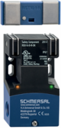
Schmersal 103003605 RFID Electronic Safety Sensor, 39.2 mm Width, IP65 Rating, 31 Series-Wired Capacity
- MPN: 103003605
- PPN: SCM-103003605
CAD
$261.69
/ EA
Available to Order
Lead times may vary. For an accurate estimate please contact us.
Looking to buy a large quantity?
To View Branch Inventory And Your Custom Pricing
Spec sheet
Description
RFID Electronic Safety Sensor, 39.2 mm Width, IP65 Rating, 31 Series-Wired Capacity
Features
- Universal coding with RFID technology
- 1 x connector plug M8
- Frontal and lateral actuation enabled
- Max. 31 sensors can be wired in series.
- Thermoplastic enclosure
- Simple mounting without additional angle
- RFID-technology for needs-based protection against tampering
Documentation & Downloads
Specifications
Electrical data - Safety digital inputs
- Designation, Safety inputs
- X1 and X2
- Test pulse duration, maximum
- 1 ms
- Classification ZVEI CB24I, Sink
- C1
Current consumption of the safety inputs5 mA
Test pulse interval, minimum100 ms
Classification ZVEI CB24I, SourceC1 | C2 | C3
Electrical data - Serial diagnostic SD
- Designation, Serial diagnostic SD
- OUT
- Design of control elements
- short-circuit proof, p-type
Operation current150 mA
Wiring capacitance50 nF
Electrical data
- Operating voltage
- 24 VDC -15 % / +10 % (stabilised PELV power supply)
- No-load supply current I
- 35 mA
- Operating current
- 600 mA
- Time to readiness, maximum
- 2,000 ms
Operating current, minimum0.5 mA
Rated operating voltage24 VDC
Required rated short-circuit current100 A
Switching frequency, maximum1 Hz
Note
- Note (General)
- Evaluation requirements: dual-channel safety input, suitable for p-type sensors with NO function. The safety-monitoring module must tolerate internal functional tests of the sensors with cyclic switch-off of the sensor outputs for max. 0.5 ms. Short-circuit recognition by the evaluation is not necessary.
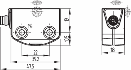
Mechanical data - Dimensions
- Length of sensor
- 29.5 mm
- Height of sensor
- 18 mm
Width of sensor39.2 mm
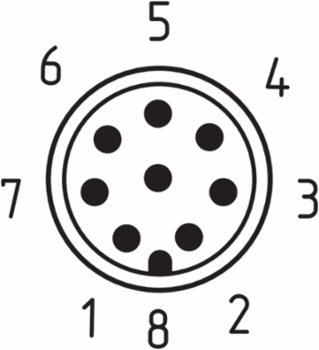
Pin assignment
- PIN 1
- A1 U | : White
- PIN 3
- A2 GND: Green
- PIN 5
- serial diagnostic output OUT Grey
- PIN 7
- Y2 safety output 2: Blue
PIN 2X1 safety input 1: Brown
PIN 4Y1 safety output 1: Yellow
PIN 6X2 safety input 2: Pink
PIN 8IN serial diagnostic input Pink
Ambient conditions - Insulation values
- Rated insulation voltage U
- 32 VDC
- Overvoltage category
- III
Rated impulse withstand voltage U0.8 kV
Degree of pollution3
Scope of delivery
- Scope of delivery
- Actuator must be ordered separately.
General data - Features
- Serial diagnostics
- Yes
- Cross-circuit detection
- Yes
- Safety functions
- Yes
- Integral system diagnostics, status
- Yes
- Number of semi-conductor outputs with signaling function
- 1
- Number of series-wiring of sensors
- 31
Short circuit detectionYes
Series-wiringYes
CascadableYes
Number of LEDs3
Number of fail-safe digital outputs2
General data
- Standards
- EN ISO 13849-1 | EN IEC 60947-5-3 | EN IEC 61508
- Coding level according to EN ISO 14119
- Low
- Frequency band RFID
- 125 kHz
- Housing construction form
- Block
- Sensor topology
- Sensor for series wiring
- Active area
- Glass-fibre, thermoplastic
- Reaction time, maximum
- 100 ms
- Reaction time, switching off safety outputs via actuator, maximum
- 100 ms
CodingUniversal coding
Working principleRFID
Transmitter output RFID, maximum-6 dB/m
Installation conditions (mechanical)not flush
Enclosure materialPlastic, thermoplastic, self-extinguishing
Gross weight60 g
Duration of risk, maximum200 ms
Safety classification
- Standards
- EN ISO 13849-1 | EN IEC 61508
- Category
- 4
- PFD value
- 1.20 x 10⁻⁴
- Mission time
- 20 Year(s)
Performance Level, up toe
PFH value6.80 x 10⁻¹⁰ /h
Safety Integrity Level (SIL), suitable for applications in3
Electrical data - Safety digital outputs
- Designation, Safety outputs
- Y1 and Y2
- Output current, (fail-safe output), maximum
- 0.25 A
- Voltage drop U
- 1 V
- Voltage, Utilisation category DC-12
- 24 VDC
- Voltage, Utilisation category DC-13
- 24 VDC
- Test pulse interval, typical
- 1000 ms
- Classification ZVEI CB24I, Source
- C2
Rated operating current (safety outputs)250 mA
Design of control elementsshort-circuit proof, p-type
Leakage current I0.5 mA
Current, Utilisation category DC-120.25 A
Current, Utilisation category DC-130.25 A
Test pulse duration, maximum1 ms
Classification ZVEI CB24I, SinkC1 | C2
Ambient conditions
- Degree of protection
- IP65 | IP67
- Storage and transport temperature, minimum
- -25 °C
- Relative humidity, maximum
- 93 %
- Resistance to vibrations
- 10 … 55 Hz, amplitude 1 mm
- Permissible installation altitude above sea level, maximum
- 2,000 m
Ambient temperature-25 ... +65 °C
Storage and transport temperature, maximum+85 °C
Note (Relative humidity)non-condensing | non-icing
Restistance to shock30 g / 11 ms
Mechanical data - Connection technique
- Termination
- Connector M8, 8-pole
- Note (series-wiring)
- Unlimited number of devices, oberserve external line fusing, max. 31 devices in case of serial diagnostic SD
Note (length of the sensor chain)Cable length and cross-section change the voltage drop dependiing on the output current
Mechanical data - Switching distances according EN IEC 60947-5-3
- Typical switching distance, frontal
- 12 mm
- Assured switching distance "ON", frontal
- 10 mm
- Assured switching distance "ON", lateral
- 6 mm
- Note (S
- The specifications of the safety switching distance S | refer to a temperature range of | -10 °C ... +60 °C. For a temperature range of -25 °C ... +65 °C, S | is reduced by 2 mm.
Typical switching distance, lateral9 mm
Assured switching distance "OFF", frontal18 mm
Assured switching distance "OFF", lateral15 mm
Note (switching distance)Axial misalignment, a horizontal and vertical misalignment of the safety sensor and the actuator are tolerated. The possible misalignment depends on the distance of the active surfaces of the sensor and the actuator. The sensor remains active within the tolerance range.
Mechanical data
- Actuating panels
- lateral | front side
- Hysteresis (Switching distance), maximum
- 2 mm
- Note (Repeat accuracy R)
- Axial offset: The long side allows for a maximum height misalignment (x) of sensor and actuator of 8 mm (e.g. mounting tolerance or due to guard door sagging). The axial misalignment (y) is max. ± 18 mm (see figure: Operating principle).Minimum clearance between two sensor systems 100 mm
- Type of the fixing screws
- 2x M4
Active arealateral | front
Repeat accuracy R0.5 mm
MountingA 20 mm screw length usually suffices to mount the sensor. When the mounting plates are used, we recommend 25 mm long screws.
Tightening torque of the fixing screws, maximum0.8 Nm
Accessory
- Recommendation (actuator)
- RST16-1 | RST-U-2 | RST260-1
Recommended safety switchgearPROTECT PSC1 | SRB-E-301ST | SRB-E-201LC
Approvals - Standards
- Certificates
- TÜV | cULus | FCC | IC | UKCA
Electrical data - Electromagnetic compatibility (EMC)
- Interfering radiation
- IEC 61000-6-4
EMC ratingIEC 60947-3
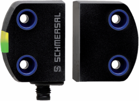
Status indication
- Note (LED switching conditions display)
- LED yellow: Operating condition | LED green: Supply voltage | LED red: Fault
Similar Products
Loading carousel layout...
Loading carousel layout...
CAD
$261.69
/ EA
Available to Order
Lead times may vary. For an accurate estimate please contact us.
Looking to buy a large quantity?
To View Branch Inventory And Your Custom Pricing
Spec sheet
CAD$261.69/ EA
Loading add to cart quantity...