Documentation & Downloads
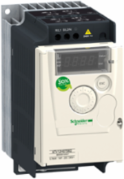
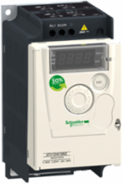
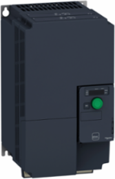
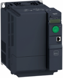
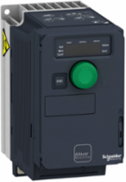
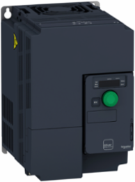
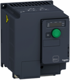
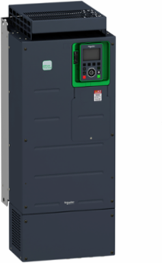
Schneider Electric ATV630D45S6 Variable Speed Drive 60 hp, 600V, IP20, Wall Mounted, Ethernet/Modbus
- MPN: ATV630D45S6
- PPN: SCH-ATV630D45S6
Available to Order
Lead times may vary. For an accurate estimate please contact us.
Loading dialog...
Looking to buy a large quantity?
To View Branch Inventory And Your Custom Pricing
Description
Variable Speed Drive 60 hp, 600V, IP20, Wall Mounted, Ethernet/Modbus
Documentation & Downloads
Specifications
Key Specifications
- Prospective Line Isc
- 70 kA
- Line Current
- 55.1 A 600 V normal duty) || 47.1 A 600 V heavy duty)
- Asynchronous Motor Control Profile
- constant torque standard || variable torque standard || optimized torque mode
- Product Or Component Type
- variable speed drive
- Switching Frequency
- 1...4.9 kHz adjustable || 2.5...4.9 kHz with derating factor
- Product Specific Application
- process and utilities
- Motor Power Hp
- 60 hp 600 V normal duty || 50 hp 600 V heavy duty
- Option Card
- slot A communication module, Profibus DP V1 || slot A communication module, PROFINET || slot A communication module, DeviceNet || slot A communication module, Modbus TCP/EtherNet/IP || slot A communication module, CANopen daisy chain RJ45 || slot A communication module, CANopen SUB-D 9 || slot A communication module, CANopen screw terminals || slot A/slot B digital and analog I/O extension module || slot A/slot B output relay extension module || slot A communication module, Ethernet IP/Modbus TCP/MD-Link || communication module, BACnet MS/TP || communication module, Ethernet Powerlink
- Range Of Product
- Altivar Process ATV600
- Ip Degree Of Protection
- IP20IEC 61800-5-1 || IP20IEC 60529
- [Us] Rated Supply Voltage
- 600 V - 15...10 %
- Type Of Cooling
- forced convection
- Nominal Switching Frequency
- 2.5 kHz
- Synchronous Motor Control Profile
- permanent magnet motor || synchronous reluctance motor
Product Destinationasynchronous motors || synchronous motors
Emc Filterwithout EMC filter
Variantstandard version
Apparent Power57.3 kVA 600 V normal duty) || 48.9 kVA 600 V heavy duty)
Communication Port ProtocolEthernet || Modbus serial || Modbus TCP
Safety FunctionSTO (safe torque off) SIL 3
Supply Frequency50...60 Hz - 5...5 %
Degree Of ProtectionUL type 1 UL 508C
Speed Drive Output Frequency0.1-500 Hz
[Us] Rated Supply Voltage600 V
Discrete Input Logic16 preset speeds
Continuous Output Current62 A 2.5 kHz normal duty || 52 A 2.5 kHz heavy duty
Device Short NameATV630
Complementary
- Discrete Input Logic
- positive logic (source) DI1...DI8), < 5 V, > 11 V || negative logic (sink) DI1...DI8), > 16 V, < 10 V
- Discrete Output Type
- relay outputs R1A, R1B, R1C 250 V AC 3000 mA || relay outputs R1A, R1B, R1C 30 V DC 3000 mA || relay outputs R2A, R2C 250 V AC 5000 mA || relay outputs R2A, R2C 30 V DC 5000 mA || relay outputs R3A, R3C 250 V AC 5000 mA || relay outputs R3A, R3C 30 V DC 5000 mA
- Exchange Mode
- half duplex, full duplex, autonegotiation Ethernet/Modbus TCP
- Net Weight
- 55 kg
- Frequency Resolution
- display unit 0.1 Hz || analog input 0.012/50 Hz
- Maximum Transient Current
- 68.2 A 60 s normal duty) || 78 A 60 s heavy duty)
- Motor Slip Compensation
- can be suppressed || automatic whatever the load || not available in permanent magnet motor law || adjustable
- Method Of Access
- slave Modbus TCP
- Local Signalling
- local diagnostic 3 LEDs || embedded communication status 3 LEDs dual colour) || communication module status 4 LEDs dual colour) || presence of voltage 1 LED red)
- Number Of Addresses
- 1-247 Modbus serial
- Transmission Rate
- 10, 100 Mbits || 4800 bps, 9600 bps, 19200 bps, 38.4 Kbps
- Analogue Input Type
- AI1, AI2, AI3 software-configurable voltage 0...10 V DC 31.5 kOhm 12 bits || AI1, AI2, AI3 software-configurable current 0...20 mA 250 Ohm 12 bits || AI2 voltage analog input - 10...10 V DC 31.5 kOhm 12 bits
- Electrical Connection
- control removable screw terminals 0.5...1.5 mm² AWG 20...AWG 16 || line side screw terminal 25...50 mm² AWG 4...AWG 1 || motor screw terminal 25...50 mm² AWG 4...AWG 1
- Height
- 822 mm
- Transmission Frame
- RTU
- Data Format
- 8 bits, configurable odd, even or no parity
- Connector Type
- RJ45 on the remote graphic terminal)Ethernet/Modbus TCP || RJ45 on the remote graphic terminal)Modbus serial
- Permissible Temporary Current Boost
- 1.1 x In 60 s normal duty) || 1.5 x In 60 s heavy duty)
- Analogue Output Number
- 2
- Minimum Switching Current
- relay output R1, R2, R3 5 mA 24 V DC
- Enclosure Mounting
- wall mounted
- Output Voltage
- <= power supply voltage
- Braking To Standstill
- by DC injection
- Protection Type
- thermal protection motor || safe torque off motor || motor phase break motor || thermal protection drive || safe torque off drive || overheating drive || overcurrent between output phases and earth drive || overload of output voltage drive || short-circuit protection drive || motor phase break drive || overvoltages on the DC bus drive || line supply overvoltage drive || line supply undervoltage drive || line supply phase loss drive || overspeed drive || break on the control circuit drive
Analogue Output Typesoftware-configurable voltage AQ1, AQ2 0...10 V DC 470 Ohm 10 bits || software-configurable current AQ1, AQ2 0...20 mA 10 bits || software-configurable current DQ-, DQ+ 30 V DC || software-configurable current DQ-, DQ+ 100 mA
Maximum Switching Currentrelay output R1, R2, R3 resistive, cos phi = 1 3 A 250 V AC || relay output R1, R2, R3 resistive, cos phi = 1 3 A 30 V DC || relay output R1, R2, R3 inductive, cos phi = 0.4 7 ms 2 A 250 V AC || relay output R1, R2, R3 inductive, cos phi = 0.4 7 ms 2 A 30 V DC
Network Number Of Phases3 phases
Type Of Polarizationno impedance
Relay Output Typeconfigurable relay logic R1 fault relay NO/NC 100000 cycles || configurable relay logic R2 sequence relay NO 100000 cycles || configurable relay logic R3 sequence relay NO 100000 cycles
Analogue Input Number3
Discrete Output Number0
Discrete Input Number8
Linearity ErrorAI1, AI2, AI3 +/- 0.15 % of maximum value analog input || AO1, AO2 +/- 0.2 % analog output
Width331 mm
Depth297 mm
Sampling Duration2 ms +/- 0.5 ms DI1...DI4) - discrete input || 5 ms +/- 1 ms DI5, DI6) - discrete input || 5 ms +/- 0.1 ms AI1, AI2, AI3) - analog input || 10 ms +/- 1 ms AO1) - analog output
Maximum Output Frequency500 kHz
Acceleration And Deceleration Rampslinear adjustable separately from 0.01...9999 s || S, U or customized
Relay Output Number3
Accuracy+/- 0.6 % AI1, AI2, AI3 for a temperature variation 60 °C analog input || +/- 1 % AO1, AO2 for a temperature variation 60 °C analog output
Input CompatibilityDI1...DI6 discrete input level 1 PLC IEC 61131-2 || DI5, DI6 discrete input level 1 PLC IEC 65A-68 || STOA, STOB discrete input level 1 PLC IEC 61131-2
Mounting Modewall mount
Physical InterfaceEthernet || 2-wire RS 485
Refresh Timerelay output R1, R2, R3)5 ms +/- 0.5 ms)
Isolationbetween power and control terminals
Quantity Per Set1
Discrete Input TypeDI7, DI8 programmable as pulse input 0-30 kHz, 24 V DC <= 30 V)
Supplyexternal supply for digital inputs 24 V DC 19-30 V), <1.25 mA overload and short-circuit protection || internal supply for reference potentiometer (1 to 10 kOhm) 10.5 V DC +/- 5 %, <10 mA overload and short-circuit protection || internal supply for digital inputs and STO 24 V DC 21-27 V), <200 mA overload and short-circuit protection
Environment
- Product Certifications
- TÜV || CSA || UL
- Standards
- UL 508C || IEC 61800-3 || IEC 61800-5-1 || IEC 61000-3-12 || IEC 60721-3 || IEC 61508 || IEC 13849-1
- Shock Resistance
- 15 gn 11 ms IEC 60068-2-27
- Noise Level
- 52 dB 86/188/EEC
- Operating Altitude
- <= 1000 m without derating || 1000...4800 m with current derating 1 % per 100 m
- Pollution Degree
- 2
- Ambient Air Temperature For Operation
- -15-50 °C without derating) || 50-60 °C with derating factor)
- Marking
- CE
- Noise Level
- 56 dB
- Relative Humidity
- 5-95 % without condensation IEC 60068-2-3
- Maximum Thdi
- <48 % with external line choke IEC 61000-3-12
Power Dissipation In Wnatural convection 205 W 600 V 2.5 kHz || forced convection 728 W 600 V 2.5 kHz
Insulation Resistance> 1 MOhm 500 V DC for 1 minute to earth
Vibration Resistance1.5 mm peak to peak 2-13 Hz)IEC 60068-2-6 || 1 gn 13-200 Hz)IEC 60068-2-6
Regulation Loopadjustable PID regulator
Overvoltage CategoryIII
Electromagnetic Compatibilityelectrostatic discharge immunity test level 3 IEC 61000-4-2 || radiated radio-frequency electromagnetic field immunity test level 3 IEC 61000-4-3 || electrical fast transient/burst immunity test level 4 IEC 61000-4-4 || 1.2/50 µs - 8/20 µs surge immunity test level 3 IEC 61000-4-5 || conducted radio-frequency immunity test level 3 IEC 61000-4-6
Volume Of Cooling Air406 m3/h
Pollution Degree2 IEC 61800-5-1
Ambient Air Temperature For Storage-40-70 °C
Operating Positionvertical +/- 10 degree
Offer Sustainability
- Mercury Free
- Yes
- Weee
- The product must be disposed on European Union markets following specific waste collection and never end up in rubbish bins
- Upgradeability
- Upgraded components available
- Environmental Disclosure
- ENVPEP1706016EN
- Circularity Profile
- ENVEOLI1706016EN
Reach RegulationReference contains Substances of Very High Concern above the threshold
China Rohs RegulationX
Rohs Exemption InformationYes
Sustainable Offer StatusGreen Premium product
Eu Rohs DirectivePro-active compliance (Product out of EU RoHS legal scope)
Similar Products
Loading carousel layout...
Loading carousel layout...
Available to Order
Lead times may vary. For an accurate estimate please contact us.
Loading dialog...
Looking to buy a large quantity?
To View Branch Inventory And Your Custom Pricing