Documentation & Downloads

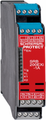
Schmersal 103037577 Safety Monitoring Module SRB200EXi-1A, 2 Safety Contacts, 100 mm Height, IP54
- MPN: 103037577
- PPN: SCM-103037577
CAD
$1409.26
/ EA
Available to Order
Lead times may vary. For an accurate estimate please contact us.
Looking to buy a large quantity?
To View Branch Inventory And Your Custom Pricing
Spec sheet
Description
Safety Monitoring Module SRB200EXi-1A, 2 Safety Contacts, 100 mm Height, IP54
Features
- Automatic reset function
- 2 safety contacts
- Suitable for signal processing of emergency stop control devices, interlocking equipment, etc
Documentation & Downloads
Specifications
Key Specifications
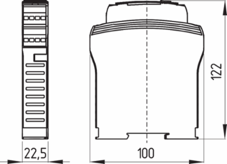
- Width
- 22.5 mm
- Depth
- 121 mm
Height100 mm
Explosion protection
- Explosion protection: regulations
- EN IEC 60079-0 | EN IEC 60079-11 | EN IEC 60079-15
- Explosion protection category
- 3G
Explosion protection zones2
Explosion protection designationII 3 G Ex nA nC IIC T5 Gc (Installation SRB, in Zone 2) | II (2) G [Ex ib Gb] IIC | II (2) D [Ex ib Db] IIIC
Electrical data
- Operating voltage
- 24 VDC -10 % / +20 %
- Current consumption
- 57 mA
- Rated AC voltage for controls at DC minimum
- 20.4 VDC
- Utilisation category AC-15
- 230 VAC
- Utilisation category DC-13
- 24 VDC
- Contact resistance, maximum
- 0.1 Ω
- Drop-out delay in case of power failure, typically
- 20 ms
- Pull-in delay at automatic start, maximum, typically
- 300 ms
- Material of the contacts, electrical
- AgSn0. self-cleaning, positive drive
Ripple voltage10 %
Rated operating voltage24 VDC
Rated control voltage at DC, maximum28.8 VDC
Utilisation category AC-152 A
Utilisation category DC-132 A
Note (Contact resistance)in new state
Drop-out delay in case of "emergency stop", maximum20 ms
Pull-in delay at RESET, typically20 ms
Note
- Note (General)
- Inductive loads (e.g. contactors, relays, etc.) are to be suppressed by means of a suitable circuit.
Mechanical data - Dimensions
- Width
- 22.5 mm
- Depth
- 121 mm
Height100 mm
Ambient conditions - Insulation values
- Rated impulse withstand voltage U
- 4 kV
- Degree of pollution
- 2
Overvoltage categoryIII
General data - Features
- Stop-Category
- 0
- Cross-circuit detection
- Yes
- Integral system diagnostics, status
- Yes
- Number of normally closed (NC)
- 2
Wire breakage detectionYes
Earth connection detectionYes
Number of LEDs5
Number of safety contacts2
General data
- Climatic stress
- EN 60068-2-78
- Gross weight
- 265 g
Enclosure materialGlass-fibre reinforced thermoplastic, ventilated
Safety classification
- Standards
- EN ISO 13849-1 | EN IEC 60947-5-1 | EN IEC 61508
- Category, Stop 0
- 4
- PFH value, Stop 0
- 2.00 x 10⁻⁸ /h
- Mission time
- 15 Year(s)
Performance Level, stop 0, up toe
Diagnostic Coverage (DC) Level, Stop 0≥ 99 %
Safety Integrity Level (SIL), Stop 0, suitable for applications in3
Common Cause Failure (CCF), minimum65
Wiring example
- Note (Wiring diagram)
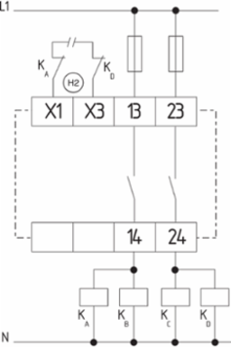
- The wiring diagram is shown with guard doors closed and in de-energised condition. | Monitoring 1 guard door(s), each with a magnetic safety sensor of the BNS range | If only one external relay or contactor is used to switch the load, the system can be classified in Control Category 3 to ISO 13849-1, if exclusion of the fault “Failure of the external contactor” can be substantiated and is documented, e.g. by using a reliable down-rated contactor. A second contactor leads to an increase in the level of security by redundant switching to switch the load off. | To secure a guard door up to PL e and Category 4 | The feedback circuit monitors the position of the contactors KA and KB. | Automatic start: The automatic start is programmed by connecting the feedback circuit to the terminals X1/X2. If the feedback circuit is not required, establish a bridge.
Other data
- Note (applications)
- Safety sensor | Guard system | Emergency-Stop button | Pull-wire emergency stop switches
Ambient conditions
- Degree of protection of the enclosure
- IP40
- Degree of protection of clips or terminals
- IP20
- Storage and transport temperature, minimum
- -40 °C
- Resistance to vibrations
- 10 ... 55 Hz, Amplitude 0.35 mm
Degree of protection of the mounting spaceIP54
Ambient temperature-25 ... +60 °C
Storage and transport temperature, maximum+85 °C
Restistance to shock30 g / 11 ms
Mechanical data - Connection technique
- Terminal designations
- IEC/EN 60947-1
Mechanical data
- Mechanical life, minimum
- 10,000,000 Operations
MountingSnaps onto standard DIN rail to EN 60715
Electrical data - Electromagnetic compatibility (EMC)
- EMC rating
- EMC-Directive
Electrical data - Digital inputs
- Conduction resistance, maximum
- 30 Ω
Similar Products
Loading carousel layout...
Loading carousel layout...
CAD
$1409.26
/ EA
Available to Order
Lead times may vary. For an accurate estimate please contact us.
Looking to buy a large quantity?
To View Branch Inventory And Your Custom Pricing
Spec sheet
CAD$1409.26/ EA
Loading add to cart quantity...